Both power factor (PF) and total harmonic distortion (THD) affect the efficiency of the power system regarding how power is converted to do actual work. In other words, it relates to “bang for the buck”. It’s like a leaky garden hose: you pay for all the water going into the hose, but you only benefit from the water that comes out the other end. The water that leaks out in other places is wasted.
Unfortunately, improving your system’s power factor and getting rid of harmonics is not as easy as repairing or replacing a leaky hose. There are some things that can be done to mitigate issues, however there are instances when all you can do is set up a system that tolerates and adapts to these problems.
This stuff might be a little difficult to understand unless you’re a whiz in calculus and trigonometry. Furthermore, it is equally difficult to explain without the use of math (which I couldn’t do anyway). Hereunder is an attempt to clarify the subject matter using plain English without subjecting the reader to convoluted explanations and advanced calculations.
POWER FACTOR (PF):
Power factor is a term used to describe energy efficiency in alternating current (AC) circuits. It is a ratio of real power to apparent power where apparent power is real power plus reactive power. Power factor is expressed as a number between 0 and 1.
![]()

Apparent power is made up of two components: real power and reactive power. Real power is doing the actual work and reactive power is waste and does not contribute to work. If you try to get a clearer understanding of these power terms from the internet, you will most likely run into a beer analogy. I for one am a big proponent of beer over math. The glass of beer is like the apparent power you are buying from a utility. However, the glass is filled with both foam and liquid beer. The foam is a nice added touch, but you really are only interested in drinking the beer. The more desirable liquid beer represents the real power while the foam portion represents the reactive power. Even though you paid for the foam, the essential substance is liquid. When you buy a glass of beer you want more beer than foam just like when you buy power you want as much real power available as possible, limiting wasted energy.
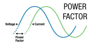
Ultimately the PF of a circuit is describing the storage elements in the circuit (inductors and capacitors) and the phase relationship between the current and voltage. When the current and voltage sine waves are in phase with one another the power factor will be higher, and thus more real power will be available.
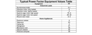
Power factor errors are caused by the utilization load, such as home appliances or industrial motors (see Typical Power Factor Equipment Values Table below). The power factor value can be used in broader terms to indicate the effects of power factor on an entire system, such as a home or an industrial facility. The utility company has more interest in power factors of the latter, as these facilities have machinery and equipment like pumps and conveyors that require induction motors to operate. Inductive or capacitive loads are the culprits responsible for negatively impacting a system’s PF and therefore the efficiency of power consumption. Some electric utility companies will penalize a consumer if the PF is below a certain number by charging an extra fee. A low power factor means that the loads in the facility are drawing more power from the grid to perform their functions.
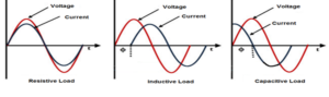
AC power is most efficient when the voltage and amperage sine waves align and remain proportional throughout the cycle.
Resistive loads use power most efficiently because their voltage and amperage sine waves are in phase. When voltage peaks are at their highest, amperage peaks are also at their highest (peaks are at the same instantaneous point) and the respective sine waves are somewhat symmetrical.
There are components and systems that force the load (amperage) and applied voltage sine waves to become misaligned. These loads are referred to as “reactive”. Reactive loads can be “inductive” or “capacitive”.
The detailed instructional information regarding reactance is too much to be contained herein, however, I will provide a brief explanation. Be aware that reactance exists and what effects it has on power circuits. Reactance is made up of capacitance and inductance, which are ways of storing energy. They introduce a time delay between changes in voltage and changes in current as the energy is stored and released. In general, inductance impedes changes in current while capacitance impedes changes in voltage. The resulting phase shift between voltage and current cycles is quantified as power factor.
In its simplest form, “power” is electricity that can be converted to do work, expressed in “watts”. The basic formula is: E (volts) X I (amps) = P (watts). Reactive loads really mess up the basic power formula. If we multiply volts X amps and they are not in alignment (based on the sine waves), this misalignment changes the relative values at any instantaneous point. Now we need a new formula. You can do the calculations if you want to:

To simplify things:
A power factor of “1” is the most efficient (totally resistive load) where all the power is used to do work.
A power factor of “0” is the least efficient (totally reactive load) where most of the power is either being stored (but not paid for, which the power company doesn’t like) or sent back to the power company (after it’s already paid for, which consumers don’t like); in either case expenses are incurred but not much work is being done.
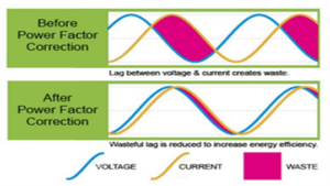
There are some power factor correction methods that may help: basically, adding capacitor banks to inductive loads or adding inductors to capacitive loads. These methods only work if the unwanted reactance is predictable and the value is constant (does not vary), otherwise it could make things worse.
TOTAL HARMONIC DISTORTION (THD):
What are harmonics?
Harmonics are a mathematical way of describing distortion to a voltage or current waveform. Harmonics are sinusoidal voltages or currents having frequencies that are whole multiples of the frequency at which the supply system is designed to operate (e.g. 50 Hz or 60 Hz).
THD Definition:
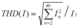
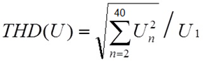
The total harmonic distortion is a measurement of the harmonic distortion present in a signal and is defined as the ratio of the sum of the powers of all harmonic components to the power of the fundamental frequency.
Right off the bat, even the definition is difficult to understand. Let’s not worry about doing the calculations and instead let’s explain it in more practical terms:
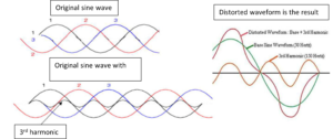
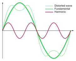
Harmonics of voltage or current are frequencies in the signal that are multiples of the frequency of the main signal. Odd number harmonics are the most troublesome (3rd, 5th, 7th, 9th….etc.). Of these, the 3rd harmonics are the most prevalent in causing overheating problems in transformers and cables.
If you’re a math whiz, here ya’ go (LOL — I shouldn’t think my lack of math skills is humorous, but I do):
So, if we’re working with a standard North American frequency of 60 Hz, the 3rd harmonic is 180 Hz (3 X 60 Hz = 180 Hz). With a European frequency of 50 Hz, the 3rd harmonic would be 150 Hz. The 3rd harmonic and multiples of the 3rd harmonic are commonly referred to as “triplen harmonics” in three-phase systems.
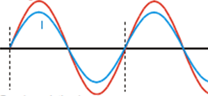
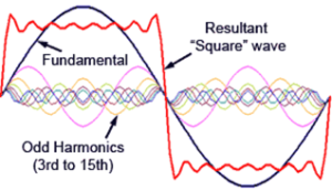
The images below depict the 3rd harmonic added to the original sine wave:
Phase and Neutral Conductors:
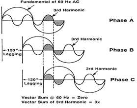
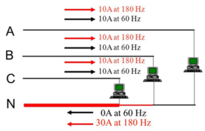
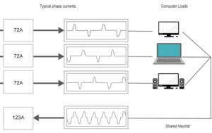
In a three-phase system, the phase voltages are displaced from each other by 120°. If the individual phases are equally loaded, the resultant current in the neutral should be zero, BUT if the power is distorted by current harmonics because the proportions of the voltage and amperage sine waves are not symmetrical or harmonics are introduced (coming back from the load), the harmonics will not cancel and will be additive on the neutral. The neutral current can exceed the current of each of the individual phase currents. In addition, the presence of harmonics in the current may subsequently lead to an overload in both the phase conductors and the neutral. This might lead to an overheating of transformers and cables and in the worst case may cause a fire.
These third-order harmonic currents do not cancel but add up arithmetically on the neutral bus, creating a primary source of excessive neutral current. Harmonics can be filtered out, but it’s usually cost-prohibitive and impractical. A common method of dealing with harmonic currents on the neutral is to oversize the neutral conductors and/or provide power distribution transformers with a high “K-factor” or “Zig-Zag” type (we will not go into transformer types or specifications here).
Where do harmonics come from?
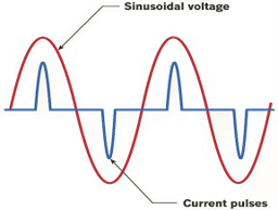
Power supplied by the utility is usually in the form of a clean (symmetrical) sine wave. As it goes through different types of loads, the voltage and current get utilized at different rates causing distortion to be reflected from the load back onto the system. In most cases harmonics are produced by “non-linear” loads.
What are non-linear loads?
This is a load where the wave shape of the current does not follow the wave shape of the applied voltage.
When current is not proportional to the voltage, the load is classified as non-linear. Non-linear loads are mostly associated with modern electronic equipment with switch mode power supplies. These are power supplies that use semiconductor switching techniques to efficiently provide a required voltage output. They are found in any device that requires a highly efficient supply. Personal computers and TV’s all have switch mode power supplies. These power supplies can also be found in process control equipment like programmable logic controller’s (PLC), power supplies, and motor drives.
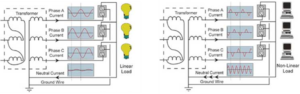
| Linear Load | Non-Linear Load |
|---|---|
 |
 |
 |
|
Non-linear loads do not have a constant impedance. As the inductors, capacitors, rectifiers, and other electronic components do their magic, the impedance changes throughout the voltage cycle. In a circuit where the impedance (resistance and reactance) is stable, the voltage will be proportional to the amperage and vice versa (the sine waves will look similar). Non-linear loads, however, take “gulps” of power in a non-symmetrical way—as the current peaks, the voltage varies, thus causing distortion in the voltage sine wave. To make matters worse, additive harmonics further distort the voltage sine wave and add load current in frequencies higher than 60 Hz.
In the early days before computers with switch mode power supplies, harmonics weren’t considered to be a big problem. As this type of equipment became prevalent throughout our lives, serious problems such as circuit fires and failing transformers were occurring. This was especially true of neutral conductors on three-phase systems.
In an attempt to diagnose what was going on, electricians were taking amp readings on circuit-related conductors. These readings were found to be well within the current capability of the equipment…..So, now what?
Well…most amp meters of that time were only capable of reading 60 Hz. Any frequencies above 60 Hz didn’t register, even though there was a considerable amount of higher frequency current flowing. We now know to diagnose harmonic problems a true RMS amp meter is required and must be capable of displaying frequencies up to at least 400 Hz. A frequency spectrum analyzer would even be better.
There are also standards in place to help mitigate harmonics. IEEE standard 519, Recommended Practices and Requirements for Harmonic Control in Electrical Power Systems states the following:
“Computers and allied equipment such as programmable controllers frequently require ac sources that have no more than a 5% harmonic voltage distortion factor, … Higher levels of harmonics result in erratic, sometimes subtle, malfunctions of the equipment that can, in some cases, have serious consequences.”
WAYS TO ADDRESS POWER QUALITY PROBLEMS:
Meters:
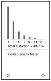
Stage lighting dimmer packs and some audio amplifiers are big contributors of THD and/or PF problems. Information provided by meters, such as the one depicted below, can benefit operators and technicians of power distribution systems, either permanently installed or portable.
This power meter is an example of the type that can display and record parameters of power specs.
Different modes of operation (depending on model) are available on the power meter.
- Standby Mode
- Voltage Current Frequency Mode (shown)
- Power Mode
- Power Factor Mode
- Total Harmonic Distortion Mode
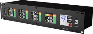
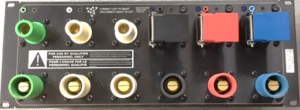
Motion Laboratories PM Series Power Meter
Double Neutrals:
To combat damage from excessive heating of neutral conductors caused by harmonic currents, double neutral feeder connections and oversized busbars can be provided on most portable power distribution units.
In addition, multi-wire branch circuits should be avoided. Common neutrals on these circuits can also be overloaded due to harmonics.
Thanks:
Jim Herrick
About the author:
Jim Herrick has over 40 years’ experience in the electrical field. Licensed in the State of New Jersey as an Electrical Contractor (License #6748) and Electrical Inspector (License #7702). Of the 40 years’ experience, 30 included work in the theatrical industry, which also included electrical equipment design for major companies in the industry.


Leave a Reply